

There is no single maximum taper that applies to every UV printer. A nearly straight part may print well on a conventional rotary without correction. A steeper cup, bottle, tube, or industrial component usually needs artwork warping, a tilting rotary axis, or both.
That is why it helps to separate uncompensated taper from machine-compensated taper. If you are evaluating a cylindrical UV printer, define the actual geometry first and then ask the supplier to prove the result on your part.
Commercial specifications show how widely machine limits can vary. Mimaki lists a 7.5° gradient angle for the Kebab HS, Roland lists a 10° maximum taper for the VersaOBJECT RC-300, and Inkcups lists a 12.5° maximum taper angle for the Helix High Throw. These are model-specific limits, not universal UV printing standards.
Put a Number on the Taper
Before comparing printers, describe the part in measurable terms. Let:
D1 = large diameter
D2 = small diameter
L = axial length over which the diameter changes
Delta D = D1 - D2
alpha = taper half-angle relative to the centerline
Taper ratio = Delta D / L
Taper % = (Delta D / L) x 100
alpha = arctan[Delta D / (2L)]
Included cone angle = 2alpha
Check the drawing convention. Some technical drawings show the half-angle relative to the centerline, while others show the full included cone angle. Confusing the two doubles or halves the value.
Worked example
A part changes from 80 mm to 70 mm in diameter over an axial length of 100 mm.
Delta D = 10 mm
Taper = 10 / 100 = 10%
alpha = arctan(10 / 200) = approximately 2.86°
Included cone angle = approximately 5.72°
| Half-angle alpha | Diameter change per 100 mm | Taper % |
|---|---|---|
| 0.5° | 1.75 mm | 1.75% |
| 1° | 3.49 mm | 3.49% |
| 2° | 6.98 mm | 6.98% |
| 5° | 17.50 mm | 17.50% |
| 7.5° | 26.33 mm | 26.33% |
| 10° | 35.27 mm | 35.27% |
| 12.5° | 44.34 mm | 44.34% |
A practical starting range
For full-wrap work with no mechanical or software compensation, keeping the taper below roughly 0.25 to 0.5° is a sensible engineering starting point. It is not an industry specification. A small local logo can sometimes tolerate more because it covers less of the circumference.
With dedicated compensation, commercial systems have demonstrated 7.5 to 10°, and specialized machines go farther. The Mimaki Kebab HS supports objects from 50 to 100 mm in diameter and up to a 7.5° taper. The Roland RC-300 supports diameters from 45 to 127 mm and up to a 10° taper.
When requesting quotations, use a table like this. A claim that the machine "supports tapered products" is not enough without measured values.
Measure the Part Before You Print It
A repeatable taper test begins at the inspection bench, not at the printer. A calibrated caliper or outside micrometer is suitable for routine factory work. Use a CMM or optical profile scanner for high-value tooling or irregular parts. Once the part is mounted, a dial indicator is the practical tool for checking rotational runout.
Define the exact print band.
Mark at least five axial measurement stations, or use 25 mm spacing on longer parts.
Measure two perpendicular diameters at every station to reveal ovality.
Repeat each measurement three times.
Record the actual distance between measurement stations.
Calculate taper from the end diameters.
Mount the part and measure total indicated runout, or TIR.
Repeat the process on several production samples, not only the engineering master.
Use one consistent record format:
Part ID | X position | D0° | D90° | Average diameter | Ovality | TIR | Calculated taper
A practical estimate of measurement uncertainty is:
u = sqrt(u2instrument + u2repeatability)
For formal quality work, report expanded uncertainty according to your normal metrology procedure.
Build a useful validation pattern
A supplier-qualification file should include:
A 1 mm registration grid
Circumferential and axial centerlines
CMYK registration crosses
0.25 and 0.50 mm line features
Solid color blocks
Fine text
360° seam marks
| Parameter | Fine or premium work | General decoration |
|---|---|---|
| Mounted-part TIR | 0.25 mm or less | 0.50 mm or less |
| Multi-color registration | 0.25 mm or less | 0.50 mm or less |
| 360° seam mismatch | 0.30 mm or less | 0.60 mm or less |
| Angular start repeatability | 0.2° or less | 0.4° or less |
Use these values as purchasing targets, not universal printer specifications. Ask the supplier to print 10 to 30 consecutive samples and report both the average and worst-case error. One flawless demonstration piece does not establish process capability.
Compensate the Artwork for Changing Circumference
A straight cylinder has one circumference. A tapered object has a different circumference at every axial position.
If the diameter changes linearly with axial position x:
D(x) = D0 + kx
k = (D1 - D0) / L
C(x) = piD(x)
S(x) = D(x) / Dref
S(x) is the approximate circumferential scaling factor when the artwork is built at a reference diameter Dref.
Scaling example
Suppose the artwork is prepared at the 80 mm end of an object that narrows to 70 mm. At the small end:
S = 70 / 80 = 0.875
The artwork width at that end should be approximately 87.5% of the width used at the 80 mm reference diameter.
Linear row-by-row scaling may be enough for a mild taper. For a steep conical part with a full-wrap graphic, use a true conical or mesh UV unwrap. That lets straight lines follow the developed frustum instead of forcing the design into a rectangle.
Some current systems automate part of this work. Mimaki's Kebab HS uses RasterLinkTools for taper-warp correction. Inkcups states that its Helix software calculates the diameter change across a tapered vessel and combines it with adjustable or programmable tooling.
A practical Illustrator and RIP workflow
Measure the geometry > build a diameter table > establish large and small circumferences > create a tapered mesh > place the artwork > warp it > add seam compensation > RIP the file > test print
For multi-color work, the encoder specification should reflect the required registration tolerance. Tangential error from angular error is:
e = piDtheta / 360
Here, theta is measured in degrees. At an 80 mm diameter, an angular error of 0.2° produces:
e = pi x 80 x 0.2 / 360 = approximately 0.14 mm
If the registration tolerance is 0.20 mm, the effective rotary control resolution should be several times finer. Around 0.05 to 0.07° per effective count or better is a reasonable engineering target for this example. Measured repeatability, however, matters more than the encoder's catalog count.
When software compensation reaches its practical limit, divide the artwork into shorter axial sections or tilt the part mechanically so the print surface stays parallel to the printhead travel plane.
Control Print Gap, Material, and UV Cure
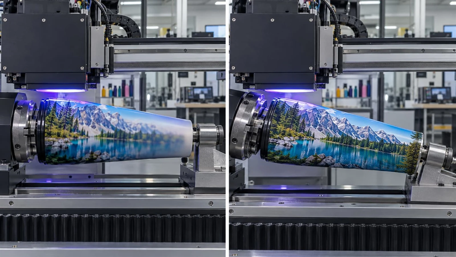
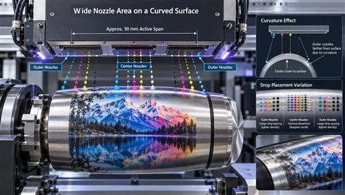
Taper changes three things at the same time: drop placement, printhead-to-surface distance, and UV lamp-to-surface distance.
If the rotary axis is not tilted correctly, one end of the object moves farther from the printhead. The longer throw can enlarge or deflect droplets, causing fuzzy text, color misregistration, and uneven white or varnish layers. The same geometry can create uneven curing because the wider and narrower ends receive UV energy from different distances or angles. Dacen's discussion of printhead geometry on cylindrical products explains why the nozzle-to-surface relationship matters.
| Substrate | Preparation | Main taper risk | Recommended validation |
|---|---|---|---|
| Glass | Degrease; use primer or plasma where required | Adhesion and reflected UV | Cross-hatch and wash test |
| Stainless steel or aluminum | Degrease; test primer | Surface-energy variation | Adhesion and abrasion test |
| PET or PC | Clean; use compatible flexible ink | Heat distortion | Cure ladder |
| PP-type plastics | Corona, plasma, or primer is often required | Low surface energy | Dyne and adhesion testing |
| Powder coating | Clean and identify coating chemistry | Variable adhesion | Batch-specific tape test |
Roland offers primer to improve UV ink adhesion on challenging rigid substrates such as glass and metal. Inkcups offers corona, plasma, and jettable-primer pretreatment options on its cylindrical systems. For a detailed process example, read Dacen's UV printing and adhesion guide for glass.
Do not prescribe one universal UV dose
UV LED systems commonly operate at wavelengths that include 365, 385, 395, and 405 nm, depending on the ink and curing system. A single mJ/cm2 value cannot cover every job. Cure response changes with photoinitiator chemistry, ink thickness, pigment load, wavelength, lamp distance, and production speed.
Instead, build a cure ladder within the ink manufacturer's approved operating window. Test reduced, nominal, and increased exposure by changing approved lamp settings, speed, or pass strategy.
Thin-wall plastics deserve extra care. Excessive curing can build enough heat to distort the part. Several controlled passes, or pinning followed by a final cure, may preserve the geometry better than one aggressive exposure.
Make the Fixture as Repeatable as the Printer
Software cannot correct a part that slips while it rotates. The fixture must locate the object radially, axially, and angularly without deforming it.
Common options for tapered parts include:
Dedicated tapered mandrels
Self-centering expanding chucks
Soft-jaw collets
Adjustable roller supports
Elastomer friction supports
Vacuum combined with mechanical or friction holding
Custom nests for severe tapers or small diameters
There is no universal clamping force. Use the lowest repeatable force that prevents angular or axial slip during the highest acceleration in the print cycle.
For precision work, target mounted runout below approximately 0.25 mm. Verify it with a dial indicator at both ends of the print band.
Setup sequence
Install the correct taper fixture.
Center the fixture on the rotary axis.
Measure TIR.
Adjust rotary tilt to match the measured taper angle.
Establish axial zero.
Establish encoder or angular zero.
Print a grid.
Measure circumference and seam errors.
Correct rotary scale or artwork compensation.
Run repeated samples to confirm stability.
Read the defect pattern. Diagonal banding points first to axial drift or tilt. A seam that moves from one part to the next suggests chuck slip or an unstable encoder zero. Error that grows gradually around the circumference points to rotary scaling or an incorrect effective diameter.
Consider an illustrative setup with 0.8 mm TIR and a 1.2 mm wrap-seam error. Replacing a generic roller fixture with a machined tapered collet might reduce TIR to 0.18 mm and seam variation to roughly 0.3 mm. The exact improvement depends on the machine, but the lesson is consistent: fixture repeatability can matter as much as nominal printer resolution.
Dacen describes custom fixtures and part-specific process setup on its industrial cylindrical UV printer page.
Validate the Part Before Buying the Printer
Send the supplier actual production samples, not just CAD dimensions. Real parts reveal ovality, coating variation, wall flexibility, fixture behavior, and curing issues that a drawing cannot show.
A practical taper-printing test package should contain:
A taper measurement worksheet
A diameter-to-angle calculator
An artwork scaling table
Registration test artwork
A cure-test matrix
A QA report template
For a sample-print request, provide the maximum and minimum diameter, axial print length, calculated taper angle, material, surface coating, wall thickness, artwork, color configuration, required registration tolerance, and target production rate.
Ask the supplier to return measured runout, seam error, registration error, cure and adhesion results, the fixture design, and confirmed production settings.
Turn the geometry into a print test
Review cylindrical printer options, then send Dacen the part dimensions, photos, artwork, substrate details, and production target for a fixture and printability discussion.
A commercial service page may offer a no-cost geometry review followed by a paid sample trial, with pricing confirmed after the supplier sees the part and tooling requirements. Only publish a one-business-day response promise if the engineering team can meet it consistently.
FAQ
Q: What maximum taper can a UV cylindrical printer handle without compensation?
A: For precision full-wrap work, roughly 0.25 to 0.5° is a conservative engineering starting range when no taper compensation is available. Even a small taper changes the circumference enough to distort artwork. A local logo may tolerate more, but the part still needs a sample test.
Q: What taper can compensated industrial printers handle?
A: Published commercial limits range from approximately 7.5° for the Mimaki Kebab HS to 10° for the Roland RC-300, while the Inkcups Helix High Throw lists 12.5°. Each value is model-specific and may also be constrained by diameter, print length, head clearance, and fixture geometry.
Q: How do I measure taper?
A: Measure the large diameter D1, small diameter D2, and axial separation L. Then calculate alpha = arctan[(D1 - D2)/(2L)]. Measure several axial stations and more than one angular orientation because ovality can create errors that a two-point calculation misses.
Q: How do I scale artwork for a tapered object?
A: Calculate the local diameter D(x), then use S(x) = D(x)/Dref. For accurate full-wrap artwork on a steep taper, use a conical unwrap or the printer manufacturer's taper-compensation software instead of one uniform scaling percentage.
Q: What fixture is best for a taper above 2°?
A: A dedicated tapered mandrel, collet, or programmable tilted rotary fixture generally gives better control than simple parallel rollers. The goal is to keep the print surface aligned while minimizing radial runout and angular slip.
Q: What test should a supplier use to prove its taper capability?
A: Use your actual part and a test file with a 360° registration grid, CMYK registration marks, fine text, solid areas, and seam targets. Print several consecutive parts, then report TIR, angular repeatability, color-to-color registration, seam mismatch, adhesion, cure condition, and reject rate. Do not rely on whether one sample simply "looks good."